The maths behind Elite's famous 3D elliptical scanner
The elliptical 3D scanner in the centre of the dashboard is one of Elite's most celebrated features, but it almost didn't make it into the game. Through almost all of the game's development, the scanner consisted of two 2D radars, one showing a top-down view of the area around the ship and the other showing a side-on view, but it never really worked that well. You can see the dual radars in this YouTube video of an early version of Elite - it's a fascinating glimpse into the development process.
Luckily, at the very last minute, after the manual had been written and the game's code had been polished until it shone, David Braben hit upon the idea of the 3D ellipse, and it was so good it just had to go in. So while Braben created the elliptical background image, Ian Bell coded the SCAN routine, all in time to update the manual and hit the publishing deadline.
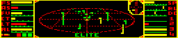
Here's the 3D scanner in the original BBC Micro version, which supports two colours for the ships (green and yellow):
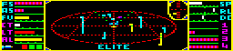
and here's the scanner in the more colourful 6502 Second Processor version, which supports seven ship colours (green, yellow, blue, red, cyan, magenta and white):
The challenge of recoding the dashboard was worth the effort, as the scanner is a thing of beauty, not only in terms of Braben's fantastic idea, which transforms the gaming experience, but also in the elegant simplicity of Bell's code. This is the last bit of code the pair wrote as anonymous undergraduates; after this, they would become rock stars, and their worlds would change forever.
Drawing the scanner
-------------------
So how does it work, this spark of genius that is so essential in making the 3D world of Elite feel so immersive? Well, to display a ship on the scanner, there are six main hoops we have to jump through.
We start with the ship's coordinates in space, given relative to our position (and therefore relative to the centre of the ellipse in the scanner, which represents our ship). Let's call the other ship's coordinates (x, y, z), with our position being at the origin (0, 0, 0).
We want to display a dot on the scanner at the ship's position, as well as a stick that drops down (or rises up) from the dot onto the scanner's ellipse.
The steps we have to perform are as follows:
- Check that the ship is within the scanner range (and stop if it isn't)
- Set X1 = the screen x-coordinate of the ship's dot (and stick)
- Set SC = the screen y-coordinate of the base of the ship's stick
- Set A = the screen height of the ship's stick
- Use these values to calculate Y1, the screen y-coordinate of the ship's dot
- Draw the dot at (X1, Y1) and draw a stick of length A from that dot (up or down as appropriate)
Note that the NES version of Elite uses sprites to display ships on the scanner, rather then drawing sticks into screen memory. The calculations are the same as in the other versions, it's just the result is drawn using a fixed set of patterns. See the deep dive on sprite usage in NES Elite for details.
Before looking at these steps individually, first we need to talk about the scanner's dimensions.
Scanner dimensions
------------------
In terms of screen coordinates, the scanner is laid out as follows.
The rectangle containing the scanner and compass has the following range of screen coordinates inside the rectangle (so we definitely don't want to draw anything outside these values, or the scanner will leak out into the surrounding dashboard and space view):
- x-coordinate from 50 to 204
- y-coordinate from 193 to 246
The scanner's ellipse is 138 screen coordinates wide and 36 screen coordinates high, and the range of coordinates is:
- x-coordinate from 56 to 192
- y-coordinate from 204 to 239
The centre of the scanner is at (124, 220).
That said, this routine restricts itself to a slightly smaller range when passing coordinates to the drawing routines, only drawing dots and sticks within this range:
- x-coordinate from 60 to 186
- y-coordinate from 194 to 246
These values are explained in the following.
Now that we know the screen area in which we are going to show our ships, let's look at the different things we have to do.
Check the ship is in range
--------------------------
Elite does a simple check to see whether to show a ship on the scanner. Ship coordinates are stored in the INWK workspace using three bytes, like this:
  x = (x_sign x_hi x_lo)
  y = (y_sign y_hi y_lo)
  z = (z_sign z_hi z_lo)
The sign bytes only use bit 7, so the actual value is in the high and low bytes (these two bytes store the absolute value, without the sign).
A ship should be shown on the scanner if bits 7 and 6 of all the high bytes are 0. This means that ships to be shown on the scanner have high bytes in the range 0-63, as 63 = %00111111, and because the sign is kept separately, it means that for ships that we show on the scanner, the following are true:
  -63 <= x_hi <= 63
  -63 <= y_hi <= 63
  -63 <= z_hi <= 63
We can now move on to calculating the screen coordinates of the dot and stick.
Calculate the x-coordinate
--------------------------
The x-coordinate is the easiest, as all we have to do is scale x so that it fits into the horizontal range of the scanner... and it turns out that the range of (x_sign x_hi) is already pretty close to the full width of the scanner (the ellipse is 138 screen coordinates wide, while the range of (x_sign x_hi) values from -63 to +63 is 127, which is in the right ballpark).
So if we take the x-coordinate of the centre of the scanner, 124, and add (x_sign x_hi), we get a range of 61 to 187, which fits nicely within the ellipse range of 56 to 192 and is quick and easy to calculate.
There is one small tweak to this, however. If we add 124 to (x_sign x_hi), then if the other ship is dead ahead of us - i.e. when (x_sign x_hi) = 0 - the dot will be drawn with the left pixel on the centre line and the right pixel just to the right of the line. This isn't a problem, but because we draw the stick down (or up) from the right-hand pixel, this means that ships that are dead ahead have a stick that lands on the ellipse just to the right of the centre line. So to fix this, we actually add 123 to get the scanner x-coordinate, as this not only moves the stick to the correct spot, it also has the benefit of making the end-points even numbers, as the range of 123 + (x_sign x_hi) is 60 to 186 (and even numbers are good news when your pixels are always 2 screen coordinates wide).
So this is how we get the screen x-coordinate of the ship on the scanner:
X1 = 123 + (x_sign x_hi)
This was the easy one. Now for the y-coordinate of the base of the stick, which is a bit more challenging.
Calculate the base of the stick
---------------------------------
We already know the x-coordinate of dot, as we just calculated that, and the stick will have the same x-coordinate as the dot, though we will add 1 when drawing it, as the stick is on the right side of the 2-pixel-wide dot. So we already know the x-coordinate of the base of the stick - now to find the y-coordinate.
The main observation here is that the scanner's ellipse is a plane in space, and for every point in that plane, the space y-coordinate is zero, and the space x- and z-coordinates determine where those points appear, either from left to right (for the x-axis) or front to back (the z-axis). We've already worked out where the base of the stick is in terms of left and right, but what about front to back?
If you think about it, points on the ellipse that are further in front of us will be further up the screen, while those behind us will be lower down the screen. It turns out that this is an easy way to work out the y-coordinate of the base of the stick - we just take the space y-coordinate and scale it so that it fits into the height of the ellipse on-screen. As long as we reverse things so that large positive y-coordinates (far in front of us) are scaled to smaller screen y-coordinates (higher up the screen), this should work pretty well.
The maths for this is relatively simple. We take (z_sign z_hi), which is in the range -63 to +63, divide it by 4 to get a range of -15 to +15, and then negate it. We then add this to the coordinate of the centre of the ellipse, which is at screen y-coordinate 220, to get the following:
SC = 220 - (z_sign z_hi) / 4
This is in the range 205 to 235, which is really close to the range of y-coordinates of the ellipse on-screen (204 to 239), and fits within the ellipse nicely.
Next, we need to work out the height of the stick, and then we'll have all the information we need to draw this thing.
Convert the stick height
------------------------
The stick height should be a signed number that contains the number of pixels in the stick, with the sign set so that we can get the dot's y-coordinate by adding the height to the y-coordinate of the base of the stick. This means that we want the following to be true:
- The stick height should be negative for dots above the ellipse (as the dot is above the base of the stick, so it has a lower y-coordinate)
- The stick height should be zero for dots on the ellipse
- The stick height should be positive for dots below the ellipse (as the dot is below the base of the stick, so it has a lower y-coordinate)
The main observation here is that the length of the stick is effectively the same as the ship's y-coordinate in space, just negated. Specifically:
- If the y-coordinate is 0, then the dot is in the plane of the ellipse and there is no stick
- If the y-coordinate is positive, then the ship is above us and the stick length should be negative
- If the y-coordinate is negative, then the ship is above us and the stick length should be positive
- The further the ship is above or below us, the longer the stick
It turns out that it's good enough just to scale the y-coordinate to get the stick length. Sure, if you were building an accurate scanner than the stick length would also have to be scaled for reasons of perspective, but this is an 8-bit space simulation from 1984 where every processor cycle counts, and the following approximation is easily good enough.
It also turns out that dividing the y-coordinate by 2 does a good enough job. We take (y_sign y_hi), which is in the range -63 to +63, and divide it by 2 to get a range of -31 to +31. As we noted above, the y-coordinate for the base of the stick is in the range 205 to 235, so this means the range of screen y-coordinates for our dots comes out as 174 to 266.
But this is a bit of a problem - the dashboard only covers y-coordinates from 193 to 246, so quite a few of the more distant dots will end up spilling out of the dashboard if we don't do something about it. The solution is pretty simple - if the dot is outside of the dashboard limits, we move it back inside. This does mean that the dots and sticks of distant ships don't behave correctly - they get shifted up or down to keep them within the dashboard, which isn't correct - but somehow our brains don't seem to care. The stick heights still remain correct, and the orientation of these outliers is still generally in the right direction, so we can get away with this simplification.
In terms of this clipping, we actually clip the dot's y-coordinate so that it is in the range 194 to 246, rather than 193 to 246. This is because the double-height dot-drawing routine at CPIX2 takes the coordinate of the bottom row of the dot, so we have to restrict it to a minimum of 194, as passing 193 would draw a dot that overlapped the top border of the dashboard.
So this is how we calculate the stick height from the ship's y-coordinate in space:
A = - (y_sign y_hi) / 2
and clip the result so that it's in the range 193 to 246. So now we have all the information required to draw the ship on the scanner, and to erase it later (which we do by drawing it a second time).