Squeezing two patterns into one tile using separate bitplanes
In the deep dive on understanding the NES for Elite, we saw how the pattern tables in the PPU's VRAM store patterns in four colours. This is the standard way of looking at NES graphics, and for most NES games, it makes sense: tiles contain four colours, and you can set those colours via the attribute tables.
For the static screens of Elite, like the charts and status pages, this explanation works nicely. But for the 3D wireframe space view, we need to look at the PPU in very different terms. Instead of thinking about four-colour patterns, we need to think about monochrome bitplanes, so let's see what that means.
Bitplanes in the PPU
--------------------
Bitplanes are a bit of a mind-bender, but they are so core to the way Elite works that it's worth taking time to really understand what's going on here. First up, it's important to realise that bitplanes are just a different way of looking at graphics in the NES; the underlying technology is exactly the same whether we're talking about four-colour patterns or bitplanes, we're just choosing to interpret the data differently.
Essentially, a four-colour screen is the equivalent of two two-colour screens, merged together. In this case, we talk about the four-colour screen containing two bitplanes. To see how this works, consider the following example, which shows a slightly garish asterisk in the standard four-colour PPU structure, shown using a yellow, red and orange palette (see the deep dive on understanding the NES for Elite for an explanation of this diagram):
  $00 = %00000000
  $00 = %00000000 -- Bit 0 of each pixel ---+
  $10 = %00001000                           |
  $10 = %00001000                           |
  $7C = %00111110                           v
  $10 = %00001000        00 00 00 00 00 00 00 00          0 0 0 0 0 0 0 0
  $10 = %00001000        00 00 00 00 00 00 00 00          0 0 0 0 0 0 0 0
  $00 = %00000000        00 00 10 00 01 00 10 00          0 0 2 0 1 0 2 0
                         00 00 00 10 01 10 00 00          0 0 0 2 1 2 0 0
                         00 00 01 01 11 01 01 00   --->   0 0 1 1 3 1 1 0
  $00 = %00000000        00 00 00 10 01 10 00 00          0 0 0 2 1 2 0 0
  $00 = %00000000        00 00 10 00 01 00 10 00          0 0 2 0 1 0 2 0
  $44 = %00100010        00 00 00 00 00 00 00 00          0 0 0 0 0 0 0 0
  $28 = %00010100                          ^
  $10 = %00001000                          |
  $28 = %00010100                          |
  $44 = %00100010 -- Bit 1 of each pixel --+
  $00 = %00000000
If you look closely, you can see that our asterisk is made up of a red "+" shape and a yellow "x" shape. The "+" shape comes from the top pattern, while the "x" shape comes from the bottom pattern. In the standard four-colour model, these combine to make a slightly ugly four-colour asterisk, but if we think of the exact same data using bitplanes, things look a bit different.
In this standard model, we get the final four-colour picture by fetching bit 0 from the top pattern and bit 1 from the bottom pattern. This gives us a two-bit colour number in the range 0 to 3 (i.e. %00 to %11). But when thinking about bitplanes, instead of this combination of bits, we don't combine the two patterns at all, we just think of them as two completely unrelated patterns, each of which has pixels that are either on or off - in other words, we think of them as two separate monochrome images. Visually, then, we can interpret the exact same data like this:
  $00 = %00000000          0 0 0 0 0 0 0 0
  $00 = %00000000          0 0 0 0 0 0 0 0
  $10 = %00001000          0 0 0 0 1 0 0 0
  $10 = %00001000          0 0 0 0 1 0 0 0
  $7C = %00111110   --->   0 0 1 1 1 1 1 0
  $10 = %00001000          0 0 0 0 1 0 0 0
  $10 = %00001000          0 0 0 0 1 0 0 0
  $00 = %00000000          0 0 0 0 0 0 0 0

  $00 = %00000000          0 0 0 0 0 0 0 0
  $00 = %00000000          0 0 0 0 0 0 0 0
  $44 = %00100010          0 0 2 0 0 0 2 0
  $28 = %00010100          0 0 0 2 0 2 0 0
  $10 = %00001000   --->   0 0 0 0 2 0 0 0
  $28 = %00010100          0 0 0 2 0 2 0 0
  $44 = %00100010          0 0 2 0 0 0 2 0
  $00 = %00000000          0 0 0 0 0 0 0 0
Each of these patterns is said to be in a different "bitplane". The definition of a bitplane is "the set of bits stored at the same relative position in each byte", so in this case bitplane 0 is the set of data stored in bit 0 of the pattern table (i.e. the red "+"), and bitplane 1 is the set of data stored in bit 1 of the pattern table (i.e. the yellow "x"). The four-colour pattern table in the PPU's VRAM therefore contains two bitplanes, each of which contains an image with two colours.
Extracting bitplanes
--------------------
The wireframe Elite space view is monochrome - it uses black and cyan as its two colours. The colourful stardust particles and laser sights are added later using hardware sprites (see the deep dive on sprite usage in NES Elite for details), but the underlying ships are always cyan on black (or, when they fly in front of the sun, black on cyan). The space view can therefore be represented in just one bitplane, as it is composed of monochrome patterns.
It's perhaps no surprise to find that the pattern table in the PPU's VRAM contains two space views at the same time, one in each bitplane. One of these bitplanes is visible at any one time, and the other is hidden. This brings us to the magic ingredient of bitplanes: the space view palettes.
Consider these two NES palettes. First, we have a palette with the background colour in entries 0 and 2 (so they are black, or colour $0F, as that's the background colour that Elite chooses) and the foreground colour in entries 1 and 3 (so they're light cyan, or $2C):

Second, we have a palette with the background and foreground colours switched around in the second and third entries, like this:

Now consider the combined image that the PPU created from our two separate bitplanes above, which is what gets displayed on screen by the PPU if we apply our original yellow, red and orange palette:
  00 00 00 00 00 00 00 00          0 0 0 0 0 0 0 0
  00 00 00 00 00 00 00 00          0 0 0 0 0 0 0 0
  00 00 10 00 01 00 10 00          0 0 2 0 1 0 2 0
  00 00 00 10 01 10 00 00          0 0 0 2 1 2 0 0
  00 00 01 01 11 01 01 00   --->   0 0 1 1 3 1 1 0
  00 00 00 10 01 10 00 00          0 0 0 2 1 2 0 0
  00 00 10 00 01 00 10 00          0 0 2 0 1 0 2 0
  00 00 00 00 00 00 00 00          0 0 0 0 0 0 0 0
Now, let's apply the first palette above, which defines colours 0 and 2 as black and colours 1 and 3 as cyan. Our combined image now looks like this on-screen:
  00 00 00 00 00 00 00 00          0 0 0 0 0 0 0 0
  00 00 00 00 00 00 00 00          0 0 0 0 0 0 0 0
  00 00 10 00 01 00 10 00          0 0 2 0 1 0 2 0
  00 00 00 10 01 10 00 00          0 0 0 2 1 2 0 0
  00 00 01 01 11 01 01 00   --->   0 0 1 1 3 1 1 0
  00 00 00 10 01 10 00 00          0 0 0 2 1 2 0 0
  00 00 10 00 01 00 10 00          0 0 2 0 1 0 2 0
  00 00 00 00 00 00 00 00          0 0 0 0 0 0 0 0
And now let's apply the second palette to the exact same image. The second palette defines colours 0 and 1 as black and colours 2 and 3 as cyan, so our combined image now looks like this on-screen:
  00 00 00 00 00 00 00 00          0 0 0 0 0 0 0 0
  00 00 00 00 00 00 00 00          0 0 0 0 0 0 0 0
  00 00 10 00 01 00 10 00          0 0 2 0 1 0 2 0
  00 00 00 10 01 10 00 00          0 0 0 2 1 2 0 0
  00 00 01 01 11 01 01 00   --->   0 0 1 1 3 1 1 0
  00 00 00 10 01 10 00 00          0 0 0 2 1 2 0 0
  00 00 10 00 01 00 10 00          0 0 2 0 1 0 2 0
  00 00 00 00 00 00 00 00          0 0 0 0 0 0 0 0
Those shapes look familiar - the first one is the "+" image in bitplane 0, while the second one is the "x" image in bitplane 1. So what we have here are two palettes that can be applied to a normal pattern from the NES pattern table, and one displays the image in bitplane 0 while hiding the image in bitplane 1, and the other displays the image in bitplane 1 while hiding the image in bitplane 0.
The upshot is that we can display an entire monochrome space view on-screen using bitplane 0 of the pattern table, while bitplane 1 remains invisible. We can then update the contents of bitplane 1 in the PPU, which won't affect the screen as bitplane 1 is invisible. When we have finished updating bitplane 1 with the updated space view, we can swap the palette so the bitplane 0 instantly disappears and bitplane 1 instantly appears, and we can then clear down bitplane 0 and redraw it, ready for the next swap.
This concept is at the heart of the graphics engine in NES Elite, so let's summarise what we've just seen.
A quick recap
-------------
To summarise, by thinking about the PPU pattern tables in terms of bitplanes, and by applying one of two simple palettes, we can use the PPU to store two completely independent monochrome screens, one of which is visible while the other is hidden, and we can flip between then instantly. This is how Elite achieves such smooth wireframe graphics, despite the huge amount of data that needs to be sent to the PPU for each screen update.
Of course, having smooth graphics is not the same thing as having a fast framerate, and NES Elite does feel a fair bit slower than the BBC Micro version. But there is no flicker at all and the transitions between frames are instant, with no screen-tearing or artifacts, and that's an important improvement if you're used to the flickery ships of BBC Micro Elite.
If bitplanes are still confusing, then ponder the following:
- Bitplanes are a bit like the red-blue filters in cheap 3D glasses. The 3D "image" is printed with one eye's image in blue and the other eye's image in red. If you look through the red lens, then you can see the image printed in blue, but not the image in red, and if you look through the blue lens you can see the image in red, but not the image in blue. The 3D "image" contains two separate images, one in the blue bitplane and one in the red bitplane, and the lenses effectively apply different palettes to extract the two images. See the Wikipedia entry on anaglyph 3D images for more on this effect.
- The two bitplanes fit together in the pattern table like the two parts of a zip (or a zipper, if you prefer that term). Think of the teeth along each side of the zip as being individual monochrome 8x8-pixel patterns. When the zip is zipped together, the zip takes one tooth from one side, then another tooth from another side, and so on. When zipped up, the closed zip contains the two separate parts of the zip in one structure, exactly like the two separate images in the two separate bitplanes being interleaved in 8-byte chunks in the PPU's pattern table.
- A number of 8-bit games implement smooth graphics using a very similar technique called colour cycling, and the bitplane approach described here is effectively just a colour cycle with an added layer of PPU data structures. For example, Aviator on the BBC Micro uses colour cycling to flip between two separate monochrome screens in a four-colour screen mode, which is very similar to NES Elite (it's just black-and-white rather than black-and-cyan). See the deep dive on flicker-free animation through colour cycling in my Aviator project for more details.
- You can think of the NES version as containing two separate BBC Micro mode 4 screens, one in each bitplane. The monochrome mode 4 uses 8 bytes to store each character block, with one bit per pixel, so each character block is identical in structure to each pattern in the pattern buffer - in other words, each of the BBC's character blocks is the same as a pattern in one bitplane. The NES version then adds the nametable system on top of this to actually display the screen, but in terms of data structure, each bitplane is essentially the same as one BBC Micro screen.
Now that we've talked about bitplanes, let's have a look at how bitplanes and the graphics buffers work together. If you haven't already, you might want to read the deep dive on the pattern and nametable buffers, as the following won't make much sense otherwise.
Bitplanes vs buffers
--------------------
Before going any further, it's important to emphasise that the concept of bitplanes only applies to patterns, and not nametables or attributes. It's also worth noting that the fact that there are two separate bitplanes is nothing to do with the fact that there are two sets of graphics buffers and two sets of tables in the PPU. It's easy to get these multiple sets of two confused, but the number of bitplanes is a property of the four-colour NES graphics system, and nothing else.
To be more specific, it turns out that when sending data to the PPU, we only ever send bitplane-based graphics into pattern table 1 in the PPU's VRAM. The PPU-sending code in Elite is written to be highly generic, but the destination address for bitplane-based pattern data (as stored in the ppuPatternTableHi variable) is initialised with the address of pattern table 1 in VRAM (i.e. $1000), and it is never changed again.
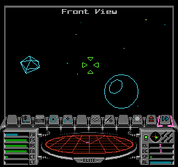
To see what this means, consider this deep space screenshot:
If we look at the contents of pattern table 0 for this screen, then it looks like this:
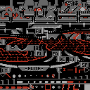
And if we look at the contents of pattern table 1 for this screen, then it looks like this:
The patterns in pattern table 0 are all fixed, in that they are sent to the PPU when the space view is initialised and aren't changed again (see the deep dive on views and view types in NES Elite for details). In pattern table 1, this is also true of most of the first four rows of patterns, all the way to the end of the pre-rendered vertical line patterns. We then see the "Front View" text for the top of the screen, which can vary depending on the view name and whether there are any in-flight messages to show, and the rest of the pattern table is taken up by the line patterns that are drawn by the line-drawing routines (see the deep dive on drawing lines in the NES version to see how these are created).
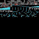
Only the line patterns use bitplanes. They use bitplanes to store two separate monochrome patterns in each of the 8x8-pixel PPU patterns, with one visible on-screen and the other hidden. If we change the palette so the hidden colour is grey rather than black and then look at pattern table 1 again, it reveals what's hidden in the other bitplane, like this:

This bitplane contains a mixture of blank tiles into which we can draw the next frame, and remnants from the previous frame which are probably in the process of being cleared out. In any case, the grey lines are a work-in-progress, which is why they are hidden.
To be even more specific, this is how the buffers get sent to the PPU when we're updating the space view:
- Nametable buffer 0 gets sent to PPU nametable 0
- Nametable buffer 1 gets sent to PPU nametable 1
- Pattern buffer 0 gets sent to bitplane 0 in PPU pattern table 1
- Pattern buffer 1 gets sent to bitplane 1 in PPU pattern table 1
For more information on how bitplanes are used to draw the screen in NES Elite, see the deep dive on drawing vector graphics using NES tiles.