The art of the impossible: vector graphics on the NES
Elite has long been lauded for doing the seemingly impossible - the fact that the game generates entire galaxies out of almost nothing (and on a 32K micro!) is still impressive, even all these years later.
But one of Elite's most astonishing achievements came seven years after the original BBC Micro version blew everyone's minds. I am, of course, talking about the 1991 NES conversion. Up until this point, nobody had managed to persuade the NES to generate smooth, flicker-free vector graphics, which was not that surprising given that the console has a tile-based graphics system that's completely unsuited to this kind of free-form drawing. As co-author Ian Bell later said:
The NES is my favourite published conversion and was not thought technically feasible until we'd done it.
This article looks at exactly how the authors achieved the "impossible", and how this supremely clever bit of coding still has the original BBC Micro routines at the heart of its graphics engine.
(By the way, this is a bit of a long read, and there are quite a few other articles that you might find useful to read first. I'll link to these as we go, but if you're in a hurry and just want to know how NES Elite works, feel free to skip straight to the summary. You can always get stuck into the details later...)
Why is NES Elite so impressive?
-------------------------------
Before we tackle the technicalities of NES Elite, let's remind ourselves why Elite would appear to be such an unsuitable candidate for conversion to the NES.
The main issue is that the NES has a tile-based screen. For games like Super Mario Bros, whose screens are obviously made up of square building blocks, this is exactly what you want: you just tell the PPU which tiles to display and where, and the PPU takes care of all the pixel-level technicalities while the game code can get on with the game logic.
Here's Mario in action:

The use of tiles here is pretty obvious. There's a fixed set of 512 patterns in the game's CHR-ROM, covering all of the game characters, platforms, coins and so on, and the real genius of the game comes in the game design and the responsiveness of the controls, while leaving the console hardware to pull it all together.
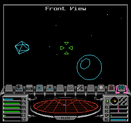
Things are pretty different in Elite. Compare the following with the Mario screen above:

The dashboard can easily be viewed in terms of tiles, but the wireframe space station is a totally different matter. It isn't at all obvious that this is a tile-based screen, but it is. In fact, it has to be, as it's on the NES.
For a game like Elite, where the contents of the space view is unpredictable and always changing, it simply isn't feasible to create the screen out of a fixed set of tiles. Luckily the NES supports CHR-RAM as well as CHR-ROM, so we can create our own tiles on-the-fly, and this is what Elite does - it draws its own patterns and allocates them to the screen tiles to create the space view. Add in some sprites for stardust, laser sights and the various dashboard elements, and we suddenly have a working game.
Of course, this makes it sound easy, but it isn't. There are lots of difficult challenges to overcome. For example:
- The NES has 512 patterns in total, split across two pattern tables. The space view portion of the NES Elite screen consists of 18 tile rows, so skipping the box edges, that's 18 by 30 tiles, or 540 tiles. That's more than the entire set of available patterns, so even if we ignore the dashboard, how does Elite use these patterns to display the space view?
- In the home computer versions of Elite, the graphics routines poke directly into screen memory, so they can draw anywhere on-screen at any time. The NES display is split up into separate 8x8 tiles, so how do the free-form graphics routines from the BBC Micro version cope with this totally different approach?
- The other versions of 6502 Elite are (in)famous for their flickery wireframe graphics, but the NES version is rock-steady and beautifully smooth. How does it do this?
- Data can only be sent to the PPU during VBlank, but Elite has an awful lot of data to send - far too much to fit into VBlank. How does it cope with this?
The first three questions are answered in the deep dives on the pattern and nametable buffers, drawing pixels in the NES version and bitplanes in NES Elite respectively, and we'll tackle the last one in this article. To that end, let's have a quick run-through of all the technologies we need to understand in order to get our heads around the NMI, the PPU, VBlank and how Elite overcomes their limitations.
A graphical recap
-----------------
Before we dive into the NMI routine at the heart of Elite's vector graphics engine, we need to cover the foundations. These are covered in a number of other deep dives, and I recommend you take a look through these before tackling the rest of this article.
First, you might want to take a look at the deep dive on understanding the NES for Elite before going any further, as I'm going to assume you know what I mean by the PPU, nametables, pattern tables and so on.
Next, we need to talk about pixel and lines. Everything you see in the wireframe space view is built up from lines, and all those lines are built up from individual pixels. The pixel-drawing and line-drawing routines are the building blocks of the NES Elite graphics system, and they have their own deep dives:
- To find out how NES Elite plots individual pixels, see the deep dive on drawing pixels in the NES version, which explains how we can draw single pixels directly into the buffers.
- To find out how NES Elite draws lines, see the deep dive on drawing lines in the NES version, which explains how diagonal, horizontal and vertical lines are efficiently drawn into the buffers.
These explain how we draw the lines and pixels of the space view, but if you want to know how the game calculates those wireframe lines in the first place, then this is covered in the deep dive on drawing ships.
Another important thing to understand is that these graphics routines draw into the pattern and nametable buffers, rather than directly into screen memory. The buffers are absolutely central to the vector graphics engine in NES Elite, so you might want to take a look at the deep dive on the pattern and nametable buffers.
Next, you'll need to understand the concept of bitplanes and how NES Elite uses them to store two totally separate patterns in each tile. For all the details, check out the deep dive on bitplanes in NES Elite.
Finally, note that the vector graphics we're talking about here only ever get sent to pattern table 1 in the PPU, and they only get sent into one bitplane in that table (the hidden bitplane). Pattern table 0 is populated with fixed tiles that are sent to the PPU when the space view is initialised, and these aren't changed again (see the deep dive on views and view types in NES Elite for details). To see what this means, consider this deep space screenshot:
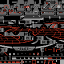
If we look at the contents of pattern table 0 for this screen, then it looks like this:
And if we look at the contents of pattern table 1 for this screen, then it looks like this:
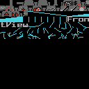
This article only deals with the patterns in pattern table 1 - i.e. in the second image above - and specifically only those patterns from the view name ("Front View") onwards. All the other patterns you can see have already been sent to the PPU by this stage and do not need updating, so they behave just like Mario's static tiles; in this article we're interested in the other tiles, the ones containing the wireframe graphics.
Incidentally, we can only use two pattern tables at the same time because NES Elite has its own split-screen system that allocates pattern table 1 to the space view and pattern table 0 to the dashboard. See the deep dive on the split-screen mode in NES Elite for details of this other way in which the NES version pays homage to the original BBC Micro game.
If you've got your head around all of the above, then you're ready to take a dive into the NMI-based routines that bring all of this technology together into Elite's killer achievement: super-smooth vector graphics on the NES.
VBlank and NMI
--------------
As discussed in the deep dive on understanding the NES for Elite, we can only send data to the PPU when it is idle and not actively updating the screen. This only happens during the short period after the PPU has finished drawing one frame and before it has started drawing the next.
This interval is called VBlank, and the system tells us when it starts by issuing an NMI interrupt. This calls the NMI handler, which is therefore called 50 or 60 times a second, depending on whether this is a PAL or an NTSC system. The NMI handler is responsible for sending all of our graphics data to the PPU before the end of VBlank. Unfortunately there is no way of telling when VBlank has finished - we can only tell when it starts.
Elite's NMI handler is the NMI routine in bank 7. This is arguably where the magic of NES Elite happens, and it's a complex and very long routine that does an awful lot. Let's see if we can summarise the main points without getting too side-tracked, starting by looking at the flow of this routine.
When NMI is called, this is what it does at a very high level:
- SendPaletteSprites - Send all the sprite data to the PPU
- SetPaletteForView - Send palette 0 for the current view to the PPU
- SendScreenToPPU - Update the screen by sending the nametable and pattern data from the buffers to the PPU, configuring the PPU registers accordingly, and clearing the buffers if required (we'll talk more about this routine below)
- ReadControllers - Read the buttons on the controllers and update the control variables
- AutoPlayDemo - If the combat demo is set to auto-play mode, automatically play the demo using the auto-play commands from the autoplayKeys tables
- MoveIconBarPointer - Move the sprites that make up the icon bar pointer and record any choices made
- UpdateJoystick - Update the joystick variables with the values from the controller
- UpdateNMITimer - Update the NMI timer, which we can use to keep track of time in places like the combat demo
- MakeSounds - Send any current music and sound effects to the APU
All of the above are run 50 or 60 times a second when the NMI routine is called at VBlank, which ensures that the music keeps playing in the background, the controllers are nice and responsive, and so on.
As far as the screen is concerned, the core routine - and by far the most complicated - is SendScreenToPPU, so let's take a look at that in more detail. It breaks down into the following steps:
- SendPalettesToPPU - If configured, send all eight palettes to the PPU
- SendBuffersToPPU - Send the graphics buffers to the PPU (we'll talk more about this routine below)
- SetPPURegisters - Set PPU_CTRL, PPU_ADDR and PPU_SCROLL for the current hidden bitplane
- ClearBuffers - Clear the graphics buffers of data that has already been sent to the PPU
Of these, the biggest step is SendBuffersToPPU, which sends the graphics buffers to the PPU. This parts breaks down like this:
- SendBarNamesToPPU - If the icon bar needs updating, send the nametable entries for the icon bar to the PPU
- SendBarPattsToPPU - If the icon bar needs updating, send the pattern table entries for the icon bar to the PPU
- SendTilesToPPU - Configure the data-sending process, unless we are continuing to send a batch of data from a previous VBlank, in which case we just pick up the configuration from where we left off
- SendPatternsToPPU - Send data from the pattern buffers to the PPU pattern tables
- SendNametableToPPU - Send data from the nametable buffers (and possibly the attribute buffers) to the PPU nametables
- SendOtherBitplane - Send the other bitplane to the PPU if required
That's a very high level breakdown of the NMI handler, and in particular the routines that send data to the PPU. Let's now work through the typical process of sending the space view to the PPU, which is controlled using the bitplane variables and the bitplane flags.
The bitplane variables
----------------------
As we discussed above, the patterns containing the space view's wireframe only ever get sent to pattern table 1 in the PPU. On top of this, they only get sent into one bitplane, specifically the hidden bitplane. The other bitplane (i.e. the one that's visible on-screen) is left alone, so the screen doesn't change while the next frame is being sent.
When we talk about bitplanes, there are three important variables that define which of the two bitplanes are being used, and for what. Each of these variables can have the value 0 (for bitplane 0) or 1 (for bitplane 1).
- drawingBitplane defines which bitplane the drawing routines draw into. Specifically, this controls which set of pattern and nametable buffers the drawing routines draw into, with pattern buffer 0 being used to store bitplane 0 of the resulting screen, and pattern buffer 1 being used to store bitplane 1.
- nmiBitplane defines which bitplane the NMI routine is currently sending to the PPU during VBlank.
- hiddenBitplane controls which bitplane is currently hidden from view (and, by extension, which bitplane is visible). This value is used to configure the PPU in the SetPPURegisters routine, and it's also responsible for setting the palette in the SetPaletteForView routine so that the correct bitplane is shown in the space view.
Looking at how the space view is drawn might help clarify how these three variables work. Let's say we're at the start of a new iteration of the main flight loop, and that we've finished drawing the previous frame into bitplane 0 and have already flagged it to be sent to the PPU. nmiBitplane will therefore be set to 0, as that's the bitplane that's now being send to the PPU in the NMI handler, and hiddenBitplane will also be 0 as we want to hide the bitplane that we're sending until we've finished sending it. We also just finished drawing into bitplane 0, so drawingBitplane will still be 0.
When we reach the start of the main flight loop, we call the FlipDrawingPlane routine to flip the value of drawingBitplane, so it is now set to 1 and all the drawing routines will draw their pixels and lines into nametable buffer 1 and pattern buffer 1 until further notice. It also calls the ClearDrawingPlane routine to clear the buffers of any data that has already been sent to the PPU, to free up as much space as possible for the new frame. The NMI is still sending nametable 0 and pattern buffer 0 to the PPU, but we're now drawing into nametable buffer 1 and pattern buffer 1, so there's no clash.
While this is going on, the NMI routine is busy sending the graphics data for the previous frame to the PPU. This effectively happens in the background, as NMI is called every VBlank without fail, though as the 6502 is a single core CPU, the main thread gets paused whenever the interrupt handler runs. Once the NMI routine has finished sending nametable buffer 0 and pattern buffer 0 to the PPU, it clears down the buffers so they can be reused, and flips hiddenBitplane to display the frame that it just sent, so hiddenBitplane is now 1. This may or may not happen before we reach the end of the flight loop, as this all happens in parallel to the code in the main loop, and is split across multiple VBlanks, depending on the amount of data that needs to be sent.
Eventually we reach the end of the main flight loop and all of the lines in the new frame have been drawn into nametable buffer 1 and pattern buffer 1, so we now flag bitplane 1 as being ready to be sent to the PPU (which we do using the bitplane flags, as described in the next section). If the NMI is still sending data from the previous frame in bitplane 0 then it will finish this off first before moving on to the new frame in bitplane 1 (though we can override this so the next frame is sent immediately if we want). If the NMI routine isn't currently sending anything to the PPU, it will start sending the new frame in bitplane 1 straight away. In either case, the handler will change nmiBitplane to 1 when it starts sending the new frame, to indicate that bitplane 1 is now being sent. So we end up with all three bitplane variables set to 1, and the cycle starts again.
As mentioned above, the process of sending data to the PPU is controlled via the bitplane flags, so let's look at those next, before talking about how we can split this lengthy process across multiple VBlanks by counting cycles.
Sending data to the PPU using the bitplane flags
------------------------------------------------
Each bitplane has its own set of bitplane flags and associated variables that control the sending of data to the PPU for that bitplane. Indeed, setting the bitplane flags for a bitplane is the normal method of telling the NMI handler to start sending that bitplane's data to the PPU, as the NMI checks the bitplane flags every time it runs, and acts on what it finds.
The bitplane flags for each bitplane are stored in the bitplaneFlags variable, with bitplane 0's flags stored at bitplaneFlags and bitplane 1's flags at bitplaneFlags+1. They look like this:
- Bit 0 is ignored and is always clear
- Bit 1 is ignored and is always clear
- Bit 2 controls whether to override the number of the last tile or pattern to send to the PPU:
- 0 = set the last tile number to lastNameTile or the last pattern to lastPattern for this bitplane (when sending nametable and pattern entries respectively)
- 1 = set the last tile number to 128 (which means tile 8 * 128 = 1024), so this means send everything up to the end of the table
- Bit 3 controls the clearing of this bitplane's buffer in the NMI handler, once it has been sent to the PPU:
- 0 = do not clear this bitplane's buffer
- 1 = clear this bitplane's buffer once it has been sent to the PPU
- Bit 4 lets us query whether a tile data transfer is already in progress for this bitplane:
- 0 = we are not currently in the process of sending tile data to the PPU for this bitplane
- 1 = we are in the process of sending tile data to the PPU for this bitplane, possibly spread across multiple VBlanks
- Bit 5 lets us query whether we have already sent all the data to the PPU for this bitplane:
- 0 = we have not already sent all the data to the PPU for this bitplane
- 1 = we have already sent all the data to the PPU for this bitplane
- Bit 6 determines whether to send nametable data as well as pattern data:
- 0 = only send pattern data for this bitplane, and stop sending it if the other bitplane is ready to be sent
- 1 = send both pattern and nametable data for this bitplane
- Bit 7 determines whether we should send data to the PPU for this bitplane:
- 0 = do not send data to the PPU
- 1 = send data to the PPU
Setting bit 7 of the relevant bitplane flags is the usual way to trigger a transfer of that bitplane to the PPU in the NMI handler. Specifically, the bitplane will be sent once any current transfer is complete, unless the current transfer's bitplane flags have bit 6 clear, in which case the new transfer will take over immediately.
As well as setting the bitplane flags to initiate a transfer of a bitplane's data to the PPU, we need to set a number of variables to tell the handler which patterns and nametable entries to transfer. Again, these variables have a separate setting for each bitplane, so firstNameTile defines the number of the first nametable tile to send when sending bitplane 0, and firstNameTile+1 defines the same value when sending bitplane 1, for example. These are the main variables that need to be set to configure the NMI handler:
- The NMI handler sends nametable entries from tile firstNameTile to lastNameTile
- The NMI handler sends patterns firstPattern to lastPattern
- The NMI handler clears the nametable buffer from tile clearingNameTile to maxNameTileToClear
- The NMI handler clears the pattern buffer from pattern clearingPattern to the last pattern that we drew into for this frame
So we can instruct the NMI handler to send data to the PPU, and can configure lots of aspects of that transfer, all via the bitplane flags and associated variables. In the space view drawing process that we analysed in the previous section, we said "we now flag bitplane 1 as being ready to be sent to the PPU (which we do using the bitplane flags, as described in the next section)", so let's look at that now.
Once we have finished drawing the space view into the buffers in part 3 of the main flight loop, we then fall through into the DrawSpaceViewInNMI routine. This works out whether we need to update the dashboard as well as the space view, before calling either DrawBitplaneInNMI or SetDrawPlaneFlags to configure the NMI to actually send the data to the PPU. These last two routines simply set the bitplane flags and associated variables, and that starts the process of sending the space view to the PPU, as follows:
- If we are already sending a bitplane, finish that off first in part 2 of SendBuffersToPPU, and then send the new bitplane via the SendOtherBitplane part of the handler.
- Otherwise jump to part 3 of SendBuffersToPPU, which checks whether either set of bitplane flags has bit 7 set ("send data to the PPU") and bit 5 clear ("we have not already sent all the data to the PPU for this bitplane"), and if so it sets that as the hidden bitplane, calls SetPaletteForView to hide and show the correct bitplanes on-screen, and then sends data to the PPU for this bitplane over multiple VBlanks.
- When all the data has been sent, SendOtherBitplane sets bit 5 of the sent bitplane's flags to disable any more sending of this bitplane until the flags are reset.
The actual sending of pattern data is done in part 5 of SendPatternsToPPU, and the way that it is done is important. The pattern buffers contain monochrome patterns, so when we send them to the PPU, we only want to send them into one bitplane - the hidden bitplane. This means we have to send the contents of the pattern buffer as individual patterns of eight bytes each, sending one pattern into the PPU's VRAM every 16 bytes (as each full pattern in the PPU is a 16-byte block, with one 8-byte bitplane in each half). In this way we leave the other bitplane alone in VRAM, and only update the hidden bitplane with our new patterns.
The sending of these blocks of eight consecutive bytes is implemented by the SEND_DATA_TO_PPU macro. This macro sends a block of bytes from memory to the PPU, so the patterns get sent to one bitplane at a time using the following macro call, which expands to send each byte one at a time via the PPU_DATA register:
SEND_DATA_TO_PPU 8
Not surprisingly, it can take a very long time to send all this data to the PPU - far longer than VBlank - so now let's take a look at how Elite copes with the sheer volume of data that needs to be sent.
Splitting data across multiple VBlanks
--------------------------------------
Sending data to the PPU can be a bit of an effort. If you ignore the almost instant DMA process that we use to send the sprite buffer to VRAM (which doesn't help us with the space view), then all data that's bound for the PPU needs be sent via the PPU registers, one byte at a time. Given the amount of data that we need to send from the NMI handler for each frame, and the fact that we can only send it during VBlank, this is a real problem.
The buffers help with this somewhat, as this means we can compose our space view and finish off all the complex mathematics of the drawing process before we need to start thinking about the PPU. But the buffers don't solve the problem, they just separate it from the drawing logic; the issue of how to send all this screen data remains.
The solution is to spread the process across multiple VBlanks, sending as much data in one VBlank as possible, and then picking up where we left off in the next VBlank. Do this enough times, and we can send all the data we need to the PPU, only flipping the palette to make the new data visible once all the new tiles have been sent.
Designing the NMI handler to pick up where we left off is not too difficult. When we want to pause the sending process at the end of the first VBlank, we simply set a few variables and flags with details of our progress before stopping the transfer, and then in the next VBlank we check those variables to see if there's a paused transfer from the previous VBlank. If there is then we continue where we left off, and if not, we check to see if any new transfers have been configured, and if there have, we start on them.
These are the variables that we set before pausin the sending process:
- If we are sending nametable entries, then we save the number of the next nametable entry to send in sendingNameTile, and the address of that entry in the nametable buffer in (nameTileBuffHi nameTileBuffLo).
- If we are sending patterns, then we save the number of the next pattern to send in sendingPattern, and the address of that entry in the nametable buffer in (patternBufferHi patternBufferLo).
- If we are clearing nametable entries from the buffer, then we save the number of the next tile to clear in clearingNameTile.
- If we are clearing patterns from the buffer, then we save the number of the next pattern to clear in clearingPattern.
You can see an example of this in part 6 of SendPatternsToPPU, which saves the variables for when we are sending patterns, before stopping. This returns us to the top-level NMI handler so it can do all the other tasks that need to be done regularly via the interrupt handler, such as playing music or checking the controllers.
So we have a system for splitting the sending of PPU data across multiple VBlanks, but how do we know when to stop sending data and leave the rest for the next interrupt? Let's look at this next.
Counting cycles
---------------
The NES tells us when VBlank starts by issuing the NMI interrupt, and this calls the NMI handler. But it doesn't tell us when VBlank ends, which is a bit of a problem if you need to stop sending data at that point. The solution is as inelegant as the hundreds of macros that we need to inject into the codebase to support the game's split-screen mode, but instead of injecting checks throughout the code, we count cycles throughout the VBlank-related parts of the NMI handler.
The basic idea is that because we know exactly how long VBlank lasts, we can count how many CPU cycles we have spent so far in the handler, and when that count reaches the known length of VBlank, we'll know that VBlank has ended. Cycle-counting is implemented in the NMI handler using a 16-bit cycle count in cycleCount(1 0), which gets set to 7433 at the start of the NMI handler (though this value is for the PAL version - see below for a discussion of the NTSC version). The cycle count represents the number of CPU cycles that we have left before the end of VBlank, so just before we perform an operation that takes a known number of cycles, we check whether we have enough cycles left in cycleCount(1 0), and only perform the operation if it will fit into the number of remaining cycles. If we do have enough cycles left in this VBlank then we can perform the operation, subtract the known number of cycles from the count, and continue on; if we don't have enough cycles, we can either abort the operation, or try a smaller variant (such as clearing a smaller batch of patterns, for example).
This cycle-count maintenance is implemented throughout the NMI handler via three macros: ADD_CYCLES, ADD_CYCLES_CLC and SUBTRACT_CYCLES. These simply add (or subtract) the macro's argument to (or from) the cycle count, with the ADD_CYCLES_CLC variant explicitly clearing the C flag in preparation for the addition (SUBTRACT_CYCLES always sets the C flag for the subtraction).
The cycle counts that need to be added or subtracted depend on the code that is being considered for running in this VBlank. Each 6502 instruction takes a known number of cycles to run - a DEX instruction, for example, takes two CPU cycles, while a LDA ($1000,X) instruction takes six cycles - so the number of cycles can be calculated exactly by simply adding up the number required for each instruction that we're thinking of running, while taking things like loops into consideration. Tools exist to count the number of cycles in blocks of code, so it's possible that the Programmers Development System (PDS) that the authors used to write NES Elite had such a profiling tool; if not, then it's always possible to count the cycles by hand, albeit a little tiresome.
The end result is that the NMI handler can ensure that it only runs its PPU-specific tasks during VBlank, switching back to the non-PPU tasks before VBlank ends. This prevents the screen from being corrupted while still enabling the game to send huge amounts of screen data to the PPU during VBlank, even though the task needs to be split across multiple interrupts and is therefore rather slower than the instant screen-updating approach in the home computer versions of Elite.
PAL vs NTSC
-----------
As noted above, the cycle count for the PAL version gets set to 7433 at the start of the NMI handler. This represents the number of CPU cycles that we can use for sending data to the PPU during VBlank, but how is this figure derived?
On all versions of the NES, the PPU takes 341 PPU cycles to draw each scanline on the screen. On the PAL version of the NES, each CPU cycle is equivalent to 3.2 PPU cycles, so that means each scanline takes 341 / 3.2 = 106.5625 CPU cycles to draw. There are 70 scanlines in VBlank in the PAL version, so that gives us a total of 70 * 106.5625 = 7459.375 CPU cycles per VBlank. I'm not entirely sure where the difference of 26 cycles comes in (7459 - 7433 = 26), but perhaps it's just a safety margin, as we would rather have our cycle count be too low than too high, to avoid overstaying our welcome.
The figures for the NTSC version of the NES are really quite different. Again, each scanline takes 341 PPU cycles, but this time each CPU cycle is equivalent to 3.0 PPU cycles, so that means each scanline takes 341 / 3.0 = 113.667 CPU cycles to draw. There are just 20 scanlines in VBlank in the NTSC version, so that gives us a total of 20 * 113.667 = 2273.334 CPU cycles per VBlank. This is about one-third of the number of VBlank CPU cycles as in the PAL version, and that's the main reason why a proper NTSC version of NES Elite doesn't exist, as fitting all of the PPU data-sending tasks into this much smaller number of CPU cycles would slow the game down massively.
Ian Bell has an "NTSC emulation" version available for download from his personal website, but this isn't a true NTSC version (and it doesn't pretend to be). The NMI timings in this variant have been changed to work with some (but not all) emulators in NTSC mode, but it isn't a full NTSC conversion, it's exactly what it claims to be, an NTSC emulation (and this how the combat demo's scroll text describes it too). In this version the cycle count is set to 6797, which is smaller than the PAL version, but still way too long to fit into the NTSC's 2237 cycles per VBlank. As a result, running the NTSC emulation on a real NTSC NES gives a corrupted screen, as you would expect.
For more detailed information on the timings in the different versions of the NES, see the NESDev wiki's cycle reference chart.
Summary
-------
So that's how NES Elite achieves the impossible, by drawing vector graphics on the NES. It's complex stuff, so let's summarise exactly how it works, and look again at the hoops that the game code jumps through when drawing each frame of the animated wireframe space view.
- Patterns, nametables and attributes for each frame are stored in two sets of graphics buffers, so the whole screen can be composed in memory before we need to think about sending the screen data to the PPU.
- Instead of poking pixels into screen memory, the pixel-drawing and line-drawing routines in NES Elite poke pixels into the pattern and nametable buffers.
- As the space view is monochrome (black and cyan), the pattern buffers are monochrome too, with one bit per pixel and eight bytes per pattern. This makes the pattern buffers almost identical in structure to the original BBC Micro mode 4 screen, just with added nametables.
- We can support two pattern tables on one screen because NES Elite has its own split-screen system that allocates pattern table 1 to the space view and pattern table 0 to the dashboard.
- Space is really empty, so we only need to store patterns for tiles that contain lines, and on average there is enough room in the last 75% of pattern table 1 to store the patterns we need for the space view.
- The horizontal and vertical line-drawing routines use pre-rendered patterns where possible to save on the number of patterns needed to display the space view (particularly the sun).
- Once the screen has been drawn into the graphics buffers, the bitplane flags are set to tell the NMI handler to start sending this data to the PPU, and the drawing bitplane is changed so we can start drawing the next frame into the other set of graphics buffers while the NMI is busy sending data in the background.
- The NMI handler sends the screen data to the PPU so that it goes into a single bitplane (i.e. the hidden bitplane) within pattern table 1.
- Because we can only send data to the PPU during VBlank, the NMI handler splits the process up across multiple VBlanks where necessary, storing the current position between interrupt calls to the handler.
- The NMI handler counts CPU cycles so that it knows when VBlank ends, and therefore when to stop sending data to the PPU during VBlank.
- Once the NMI has finished sending data, the hidden and visible bitplanes are flipped so the new frame appears instantly and the old one gets hidden.
And that's how the magic works. It's very clever stuff... and given that this is Elite we're talking about, that's really saying something.