Poking screen memory to display colour pixels in the dashboard view
Drawing four-colour pixels in the dashboard is not as straightforward as you might think. It's complicated enough drawing monochrome pixels in the two-colour mode 4 screen that Elite uses for the space view, but it's even more mind-bending in mode 5, so before you read the following, I highly recommend you take a look at the deep dive on drawing monochrome pixels in mode 4, which looks at screen addresses and plotting techniques for this simpler black-and-white mode. If monochrome plotting already makes sense to you, then let's move on to four colours, which the CPIX2 routine looks after.
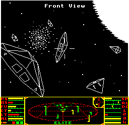
Mode 5 is used for the four-colour dashboard in the BBC Micro version:

As with mode 4, the mode 5 screen is laid out in memory using character blocks. Indeed, the character blocks are the same size and height in terms of bits and bytes, and pixel coordinates are identical in both screen modes (both screen modes are 256 coordinates wide), so as far as the end used is concerned, the screen modes are really similar. At the screen memory level, however, there are some key differences.
The main difference is that each pixel can be one of four colours rather than two, so as a result each pixel takes up twice as much memory (2 bits as opposed to 1 bit). If we look at the way character blocks are laid out in terms of bits, it looks the same as for mode 4 - here's what two neighbouring character blocks look like in both modes:
  01234567 01234567
  01234567 01234567
  01234567 01234567
  01234567 01234567
  01234567 01234567
  01234567 01234567
  01234567 01234567
  01234567 01234567
However, while in mode 4 each bit represents one pixel, so the above block would be 16 pixels across and 8 pixels high, in mode 5 each pixel takes up two bits, so the above block shows as 8 pixels across and 8 pixels high. Pixels in mode 5 are stretched out so they appear twice as wide as they are high, so everything still fits on-screen in a sensible manner.
So we know that a character block row in mode 5 consists of four pixels in one byte. The complicated part is how that byte stores those four pixels. If we consider a character row byte like this:
01234567
then the first pixel is defined by bits 0 and 4, the second by bits 1 and 5, and so on. If we split it up into nibbles:
0123 4567
then the first pixel is defined by the first bits of each nibble (0 and 4), the second is defined by the second bits of each nibble (1 and 5), and so on with bits 2 and 6, and bits 3 and 7. So consider this character row byte:
1111 0000
Each of the four bits has a 1 as the first bit and a 0 as the second bit, giving %10, or 2, so this defines four pixels in a row of colour 2. And this one:
1010 0011
contains the following pixels: %10, %00, %11 and %01, so this is a four-pixel row consisting of pixel colours 2, 0, 3 and 1.
That aside, modes 4 and 5 work in the same way. Each character row takes up 256 bytes, or exactly one page, so we can convert from screen coordinates to character blocks using the same code. We can even work out the correct row in the relevant character block in the same way, as the screen x- and y-coordinate systems are identical. The only differences are:
- How we manipulate the individual character row bytes to support the nibble system for four colours
- The fact that the y-coordinate still ranges from 0 to 256, but this time there are only 128 pixels across the screen, so each pixel effectively has two different screen coordinates (though we can easily cater for this by ignoring the last bit of the y-coordinate)
We can even use a similar system to the TWOS table that we use in PIXEL, but this time it's set up for the nibble system above. As a reminder, the TWOS table provides ready-made bytes for plotting single pixels, such as this one for plotting the third pixel in the row (out of 8):
TWOS+2 = %00100000
We can do the same for mode 5, but using the CTWOS table instead. For the third pixel in the row (out of 4), the table returns this value instead:
CTWOS+2 = %00100010
which breaks up into 0010 0010, or %11 in the third pixel. As with TWOS, we can use this byte as a mask onto a 4-pixel colour byte to work out what to poke into screen memory.
On the subject of 4-pixel colour bytes, this is what they look like for the four colours used in the dashboard:
- Colour 0: %00000000 = &00 (black)
- Colour 1: %00001111 = &0F (red)
- Colour 2: %11110000 = &F0 (yellow/white)
- Colour 3: %11111111 = &FF (green/cyan)
So aside from having two bits per pixel and four pixels per character row, mode 5 is pretty similar to the monochrome mode 4.