How Elite draws ellipses for the planet's crater, meridian and equator
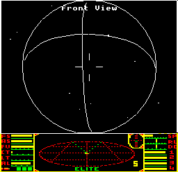
The BBC Micro and NES versions of Elite have a feature that is notably absent from all other versions of the game, from the 8-bit Commodore 64 and ZX Spectrum versions, to the 16-bit PC and 32-bit Archimedes ports. In all those other variations of Elite, planets are either plain circles or simple filled disks, but when you launch from Lave on the BBC Micro or NES, you're greeted by a planet with a rotating meridian and equator, like this:
And after a quick hyperspace to nearby Diso, the planet hanging in the distance boasts a huge crater that hurtles around the surface at speed. The BBC Micro's planets might rotate improbably fast, but they feel a lot more three-dimensional than the flat disks of the other platforms.

The key to both of these unique planetary features can be found in the ellipse routines at PLS2 and PLS22. The planet's meridian and equator are drawn as half-ellipses by calling PLS2 from part 2 of PL9, while the crater is drawn as a full ellipse by calling PLS22 from part 3 of PL9. In this deep dive we take a look at how these ellipses are drawn; for information on how the planet's features are constructed from these ellipses, see the deep dives on drawing craters and drawing meridians and equators.
Interestingly, the ellipse routines are still present in some of the other 6502-based versions, and in some cases they can even be enabled using an undocumented feature - for example, you can pause the Commodore 64 version and press "P" to enable more detailed planets, though they do slow the game down quite a bit, which is presumably why they are disabled by default. In other versions, like the Acorn Electron, the code has been completely removed to save space.
Drawing ellipses with parametric equations
------------------------------------------
The PLS22 subroutine is responsible for drawing ellipses and half-ellipses, depending on the value of the TGT parameter. Full ellipses are used when drawing planet craters, and half-ellipses are used when drawing planet meridians and equators.
The PLS22 subroutine works as follows. If we have any pair of two-dimensional vectors u and v:
  u = [ u_x ]
      [ u_y ]

  v = [ v_x ]
      [ v_y ]
and an ellipse centre point at coordinate c:
  c = [ c_x ]
      [ c_y ]
then a parametric equation of an ellipse is given by:
  [ x ]  =  [ c_x ]  +  [ u_x ] * cos(theta)  +  [ v_x ] * sin(theta)
  [ y ]     [ c_y ]     [ u_y ]                  [ v_y ]
This is a parametric equation in theta (see the Wikipedia entry on parametric equations for details). What this means is that as theta increases from 0 to 360 degrees, the x and y coordinates move accordingly, and as they do so, they plot out an ellipse.
In this case, u and v are said to be conjugate half-diameters of the ellipse (see the Wikipedia entry on conjugate diameters for details). Before we get to that, it's probably easier to understand the simpler case where u and v are perpendicular to each other, and are both axis-aligned. To illustrate this, let's set up u and v as follows:
  u = [ 2 ]
      [ 0 ]

  v = [ 0 ]
      [ 3 ]
Then the parametric equation for the ellipse simplifies into:
  [ x ]  =  [ 0 ]  +  [ 2 ] * cos(theta)  +  [ 0 ] * sin(theta)
  [ y ]     [ 0 ]     [ 0 ]                  [ 3 ]

         =  [ 2 * cos(theta) ]
            [ 3 * sin(theta) ]
We can interpret this as the parametric equation of a circle, as shown in the deep dive on drawing circles; but in this ellipse example, the x-coordinates have been stretched by a factor of 2, and the y-coordinates have been stretched by a factor of 3. This is therefore a tall ellipse aligned with the y-axis, with a horizontal radius of length 2 and a vertical radius of length 3, like this:


In the above simple example, vectors u and v represent the minor and major radii of the ellipse.
In practice, u and v do not have to be axis-aligned, or even perpendicular to each other. In general, when u and v are not perpendicular, the above parametric equation will still give us an ellipse, but now it will be rotated, and not axis-aligned. For example, if we take the following values for u and v:
  u = [ 2.0 ]
      [ 0.6 ]

  v = [ 0.6 ]
      [ 2.5 ]
then we get the following rotated ellipse:


To see this in action, check out this BBC BASIC demonstration of the Elite ellipse-drawing algorithm (link opens in a new window). This uses the Owlet engine to run the BASIC program in your browser, and you can clearly see the ellipse being drawn as the theta parameter goes from 0 to 2*PI radians (i.e. from 0 to 360 degrees) in 64 steps.
There are a number of mathematically interesting details about this parametric way of defining an ellipse:
- The above parametric equations do give an ellipse.
- The ellipse passes through the points at the ends of the u and v vectors (as shown in the above diagrams). When theta is 0, the (x, y) coordinates pass through the end of the u vector. When theta is 90 degrees, the (x, y) coordinates pass through the end of the v vector.
- When u and v are not perpendicular, u and v will end up as conjugate-radius vectors of the ellipse (see the Wikipedia entry on conjugate diameters for more on this).
This parametric method, with two non-perpendicular vectors u and v used to define the ellipse, is a fairly unusual way to plot an ellipse, but this approach is particularly convenient and efficient for drawing craters and meridians. The ellipse routine uses sine and cosine lookup-tables with just 64 points stored in them (see the deep dive on the sine, cosine and arctan tables for details). In the PLS22 routine, the variables used to represent vectors u and v are as follows:
  u = [    (XX16 K2)   ]
      [ -(XX16+1 K2+1) ]

  v = [  (XX16+2 K2+2) ]
      [ -(XX16+3 K2+3) ]
The y-coordinates are negated because BLINE expects pixel coordinates but the u and v vectors are extracted from the orientation vectors. The y-axis runs in the opposite direction in 3D space to that on the screen, so we need to negate the 3D space coordinates before we can combine them with the ellipse's centre coordinates.
Other parameters passed to PLS22 are:
  c = [ K3(1 0) ] = coordinates of the centre of the ellipse
      [ K4(1 0) ]

  TGT = the number of line segments to plot

  CNT2 = the segment number to start drawing from

  STP = step rate at which to increase the angle when drawing the ellipse
As with the circle-drawing algorithm, the ellipse routine does not use any symmetry properties of the ellipse to halve the number of points calculated, but instead relies on the pre-calculated sine and cosine tables for speed.